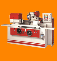
Milling Machine
A milling machine is heavy industrial equipment that uses rotary cutters to remove material from a work piece moving forward in a direction at a specified angle with the axis of the tool. Milling Machines are the most commonly used processes in the industry. It operates solely on the principle of rotary motion.
In the vertical mill the spindle axis is vertically oriented. Milling cutters are held in the spindle and rotate on its axis. The spindle can generally be extended (or the table can be raised/lowered, giving the same effect), allowing plunge cuts and drilling. There are two subcategories of vertical mills: the bed mill and the turret mill.
A turret mill has a stationary spindle and the table is moved both perpendicular and parallel to the spindle axis to accomplish cutting. Turret mills often have a quill which allows the milling cutter to be raised and lowered in a manner similar to a drill press. This type of machine provides two methods of cutting in the vertical (Z) direction: by raising or lowering the quill, and by moving the knee.
In the bed mill, however, the table moves only perpendicular to the spindle's axis, while the spindle itself moves parallel to its own axis.
Turret mills are generally considered by some to be more versatile of the two designs. However, turret mills are only practical as long as the machine remains relatively small. As machine size increases, moving the knee up and down require considerable effort and it also becomes difficult to reach the quill feed handle (if equipped). Therefore, larger milling machines are usually of the bed type.
A horizontal mill has the same sort of x – y table, but the cutters are mounted on a horizontal arbor (see Arbor milling) across the table. Many horizontal mills also feature a built-in rotary table that allows milling at various angles; this feature is called a universal table. While end mills and the other types of tools available to a vertical mill may be used in a horizontal mill, their real advantage lies in arbor-mounted cutters, called side and face mills, which have a cross section rather like a circular saw, but are generally wider and smaller in diameter. Because the cutters have good support from the arbor and have a larger cross-sectional area than an end mill, quite heavy cuts can be taken enabling rapid material removal rates. These are used to mill grooves and slots. Plain mills are used to shape flat surfaces.
 |
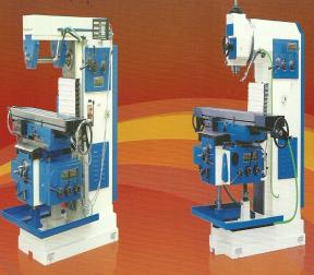
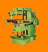
| Universal
Milling Machine |
Universal Milling Machine is manufactured using best grade materials and is available in various sizes and shapes of cutters. All these milling machines are effective in operations and are easy to maintain. The range of milling machines are outfitted with advanced features and is rapid in their operation.
FEATURES
- Base: The Base of Heavy Rigid Casting Serving also as Coolant Tank. It Provides a suitable platform for Robust Operation
- Column: The Column is again of Rigid Built. Traces are Hand Scraped and Lapped/ Ground.
- Knee: The Heavy Knee is made as a Box and Rests on a Vertical Column Equipped with Thrust Bearing and Protected from Dirt and Chips by Telescopic Covers. The Moveable Parts inside are Protected foreign matter and Coolant, The Knee being closed at the Upper End. All the Hand Wheels are Relatable. The Automatic Feeds in all three Directions are limited by means of Adjustable Feed Trip.
- Table: The Work Table is of a very Sturdy Construction and the Dovetail is Provided with an Adjustable gib. The Table has 3 T-Slots and is Provided with Coolant Channels. In the Construction of the Milling Machine Special Importance is Attached to Sturdy Construction of the Base of the Table. A Graduated Scale is Placed in order to obtain an Exact Angle Adjustment up to 45 at either Side. The Working Pressure of the Table Lead Screw is taken up though Pressure Thrust Bearings.
- Power Drive: The though an Electric Motor Flange Mounted at the Rear of the Machine. Clutch Levers are Placed within Reach on Both Side of the Column. The Driving Shafts and Spindle Shaft are bedded in Roller and Ball Bearing Respectively.
- Over Arm: The Exceptionally (Rectangular) Over Arm gives the Milling Arbor a Very Rigid Support. The Over Arm Slides Horizontally in the Dovetail Guide in Column and Can be Clamped against the Solid Location Side of Column. The Arbor Support Fixed in the Over Arm is Moveable and Can be Adjusted and Fixed in any Position. The Heavy Pair of Braces Securely Hold the Arbor and the Over Arm together thus ensuring Accuracy even under the Heaviest Cut.
|
Ask for Price |
| Technical Specifications |
|
| Model |
SUM-1B |
SUM-2B |
SUM-3B |
SUM-4B |
SUM-5B |
SUM-6B |
SUM-7B |
| Table |
| WORKING SURFACE |
1100*270 |
1300*290 |
1400*350 |
1600*360 |
1800*400 |
2000*450 |
2300*500 |
| SWIVEL |
+ - 45 DEGREE |
+ - 45 DEGREE |
+ - 45 DEGREE |
+ - 45 DEGREE |
+ - 45 DEGREE |
+ - 30 DEGREE |
FIX |
| T-SLOT NOS/ SIZE |
3/17 |
3/17 |
3/17 |
3/17 |
5/17 |
5/20 |
5/20 |
| T-SLOT CENTRE |
60 |
65 |
80 |
90 |
80 |
90 |
95 |
| DIST. FROM SPINDLE MAX/MIN |
350-0 |
400-0 |
475-0 |
550-0 |
550-50 |
600-50 |
600-50 |
| X-LONGITUDINAL TRAVEL |
500 |
650 |
775 |
900 |
1100 |
1250 |
1300 |
| Y-CROSS TRAVEL |
180 |
205 |
255 |
305 |
450 |
500 |
550 |
| Z-VERTICAL TRAVEL |
350 |
400 |
475 |
550 |
600 |
650 |
650 |
| Feeds |
| NO. OF FEEDS |
9 |
18 |
18 |
18 |
18 |
18 |
18 |
| RANGE OF LONGITUDINAL FEED/MIN |
13-200 |
13 TO 305 |
13 TO 305 |
13 TO 305 |
13 TO 305 |
13 TO 305 |
13 TO 305 |
| RANGE OF CROSS FEED/MIN |
13-200 |
13 TO 305 |
13 TO 305 |
13 TO 305 |
13 TO 305 |
13 TO 305 |
13 TO 305 |
| RANGE OF VERTICAL FEED/MIN |
5-100 |
2.5 TO 62 |
2.5 TO 62 |
2.5 TO 62 |
2.5 TO 62 |
2.5 TO 62 |
4 TO 90 |
| NO. OF RAPID FEEDS |
1 |
2 |
2 |
2 |
2 |
2 |
2 |
| LONGITUDINAL RAPID FEED/MIN |
700 |
735, 1065 |
735, 1065 |
735, 1065 |
735, 1065 |
735, 1065 |
500, 735 |
| CROSS RAPID FEED/MIN |
700 |
735, 1065 |
735, 1065 |
735, 1065 |
735, 1065 |
735, 1065 |
500, 735 |
| VERTICAL RAPID FEED/MIN |
240 |
147, 210 |
147, 210 |
147, 210 |
147, 210 |
147, 210 |
165, 25O |
| Spindle |
| NO. OF SPINDLE SPEEDS |
9 |
9 |
18 |
18 |
18 |
18 |
18 |
| RANGE OF SPINDLE SPEEDS (RPM) |
45 to 1100 |
45 to 1100 |
35 to 1800 |
35 to 1800 |
35 to 1800 |
35 to 1800 |
40 TO 2000 |
| SPINDLE TAPER |
ISO 40 |
ISO 40 |
ISO 40 |
ISO 40 |
ISO 40 |
ISO 50 |
ISO 50 |
| ARBOUR DIAMETER |
25.4 |
25.4 |
25.4 |
25.4 |
25.4 |
25.4 |
40 |
| Electrical |
| MAIN MOTOR |
3 H.P |
3 H.P |
5 H.P |
7.5 H.P |
7.5 H.P |
10 H.P |
10 H.P |
| FEED MOTOR |
2 H.P |
2 H.P |
2 H.P |
2 H.P |
3 H.P |
3 H.P |
3 H.P |
| COOLANT MOTOR |
0.1 H.P |
0.1 H.P |
0.1 H.P |
0.1 H.P |
0.1 H.P |
0.1 H.P |
0.1 H.P |
| Dimensions (Approx.) |
| OVERALL LENGTH |
1600 |
1850 |
2000 |
2100 |
2500 |
2700 |
2800 |
| OVERALL WIDTH |
1400 |
1600 |
1750 |
1950 |
2500 |
2600 |
2700 |
| OVERALL HEIGHT |
1550 |
1680 |
1800 |
1880 |
2400 |
2700 |
2800 |
| NET WEIGHT KG. |
2000 |
2600 |
3300 |
3700 |
4200 |
5000 |
6500 |
| GROSS WEIGHT KG. |
2200 |
2900 |
3600 |
4000 |
4600 |
5700 |
7500 |
|
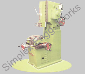
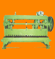
Our offered range of Slotting Machine is a retuning tool which consists of ram holding the tool reciprocates the cutting action and vertical axis of the tool while downward stroke. These slotting machines are used in industries for precise planning and slotting of materials.
|
Ask for Price |
| Specifications |
|
|
| Model |
SSM-125 |
SSM-150 |
SSM-200 |
SSM-250 |
SSM-300 |
SSM-375 |
SSM-450 |
SSM-500 |
| Working Stroke |
125 |
150 |
200 |
250 |
300 |
375 |
450 |
500 |
| Length of Ram |
200 |
560 |
560 |
735 |
810 |
900 |
1300 |
1300 |
| Vertical Adjustment of Ram |
90 |
150 |
150 |
250 |
300 |
300 |
325 |
325 |
| Center of Cutting Tools of Col |
165 |
250 |
250 |
380 |
455 |
550 |
750 |
750 |
| Working Surface of Table |
200 |
280 |
280 |
355 |
500 |
600 |
900 |
900 |
| Longitudinal Transverse of Table |
165 |
250 |
250 |
300 |
530 |
530 |
800 |
800 |
| Bore of Base |
28 |
38 |
38 |
75 |
75 |
75 |
100 |
100 |
| Cross Transverse of Table |
215 |
250 |
250 |
300 |
455 |
500 |
600 |
600 |
| Table Top to Tam |
200 |
330 |
330 |
380 |
400 |
525 |
700 |
700 |
| No. of Speeds |
2 |
2 |
2 |
2 |
4 |
4 |
6 |
6 |
| Range of Speeds |
90-170 |
60-150 |
60-150 |
46-70 |
20-70 |
20-70 |
20-70 |
20-70 |
| Motor Recommended |
1 H.P. |
1.5H.P. |
1.5H.P |
2H.P. |
3H.P. |
3H.P. |
5H.P. |
7.5H.P |
| R.P.M of Motor |
1440 |
1440 |
1440 |
1440 |
960 |
960 |
960 |
960 |
| Approx. Weight (Kg) |
350 |
800 |
800 |
1100 |
1500 |
2000 |
4500 |
4500 |
| Gross Weight (Kg) with Packing |
450 |
950 |
950 |
1300 |
1800 |
2500 |
5000 |
5000 |
|
|
|


